Goblin User Guide
Under construction! Expected completion: 28.6.23

Introduction
The Goblin is suitable for both DinSync.info RE-101 and Roland SH-101.
It is a highly accurate replication of the original CPU. To use it, you can refer to all parts of the original Roland SH-101 user manual; all functions are identical.
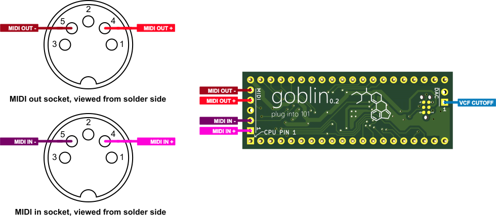
In addition to the OG functionality, the Goblin adds MIDI in and MIDI out. VCF cutoff may be controlled by MIDI note velocity and / or Continuous Controller.
Other than MIDI, the Goblin adds nothing else. The aim was to only faithfully replicate OG behaviour, but with added MIDI.
Initial preparation
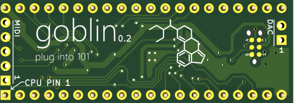
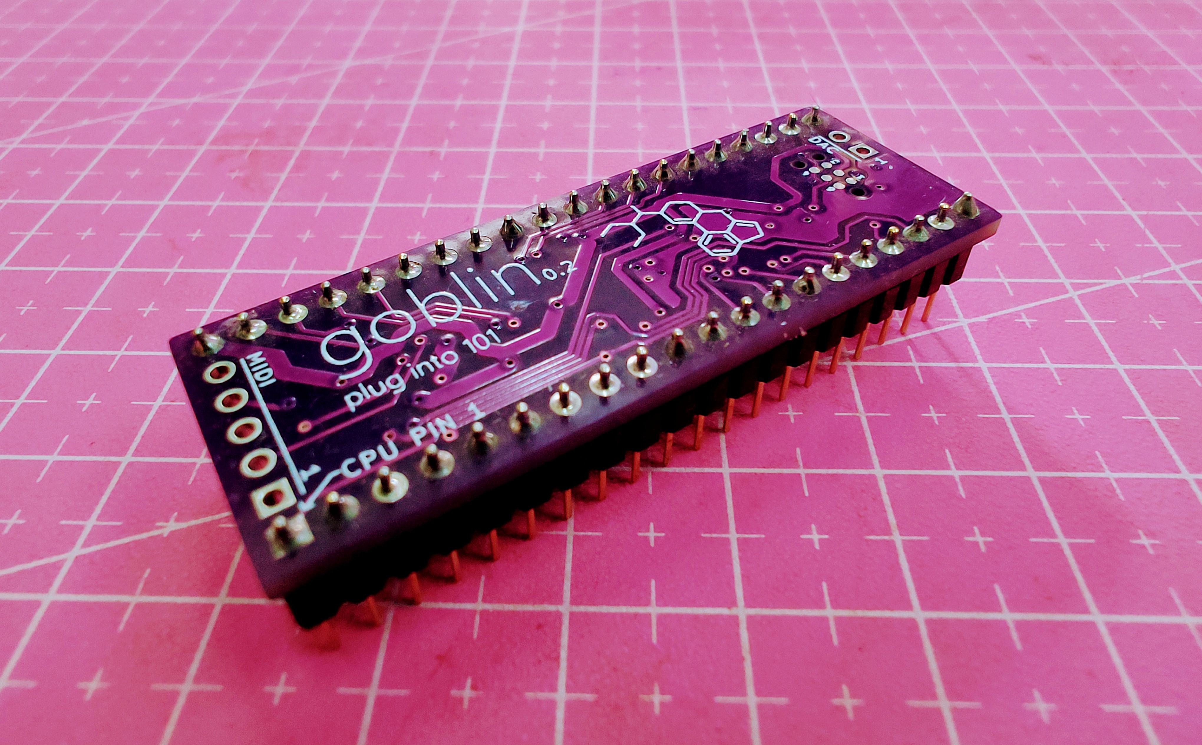
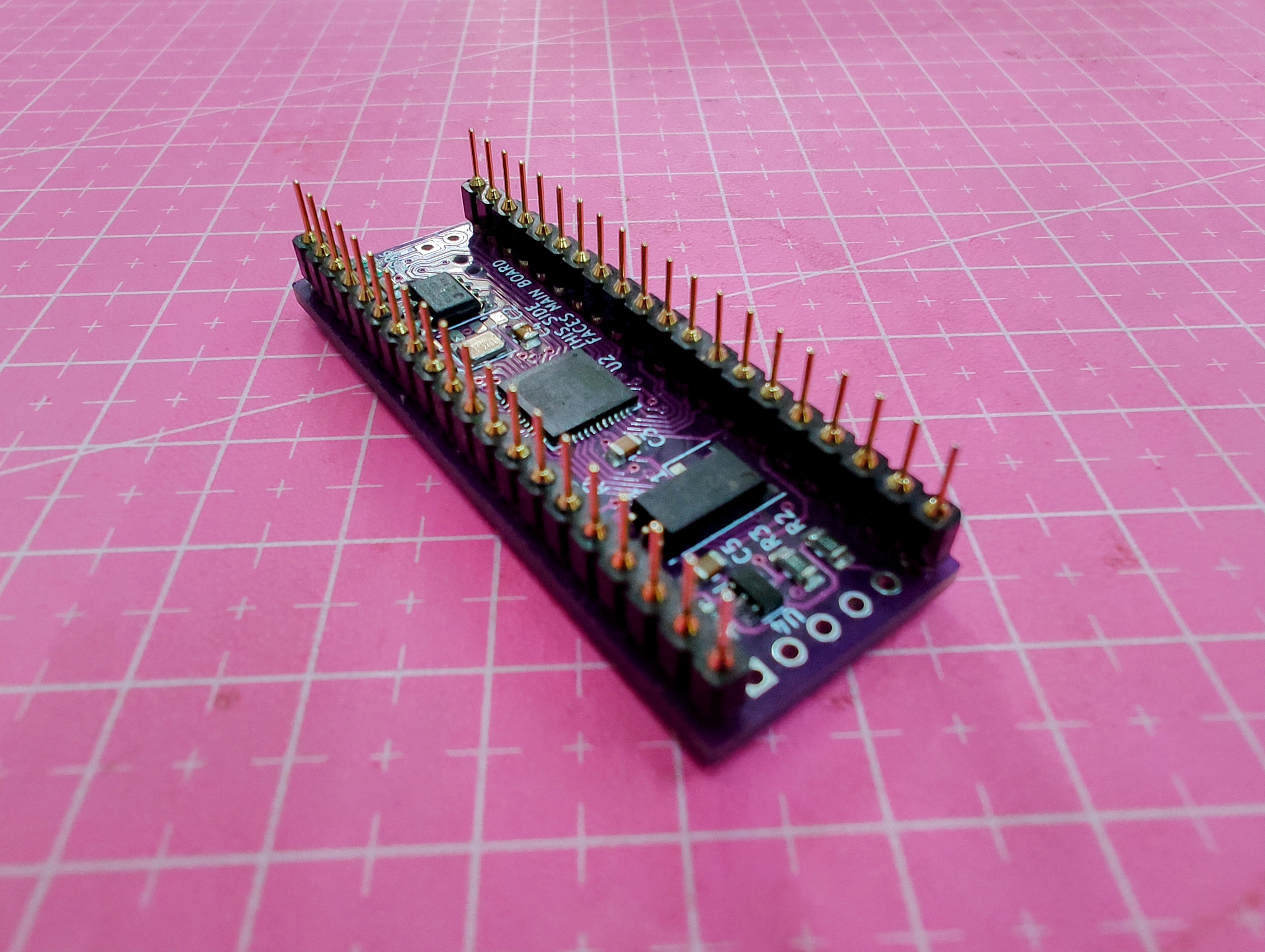
Two rows of 20-pin turned-pin headers are carefully soldered as shown. It’s essential to use turned-pin headers to ensure the Goblin will plug into an IC socket.
The Goblin is supplied tested and programmed with firmware, so you don’t need to perform any firmware programming steps before using it.
Installation
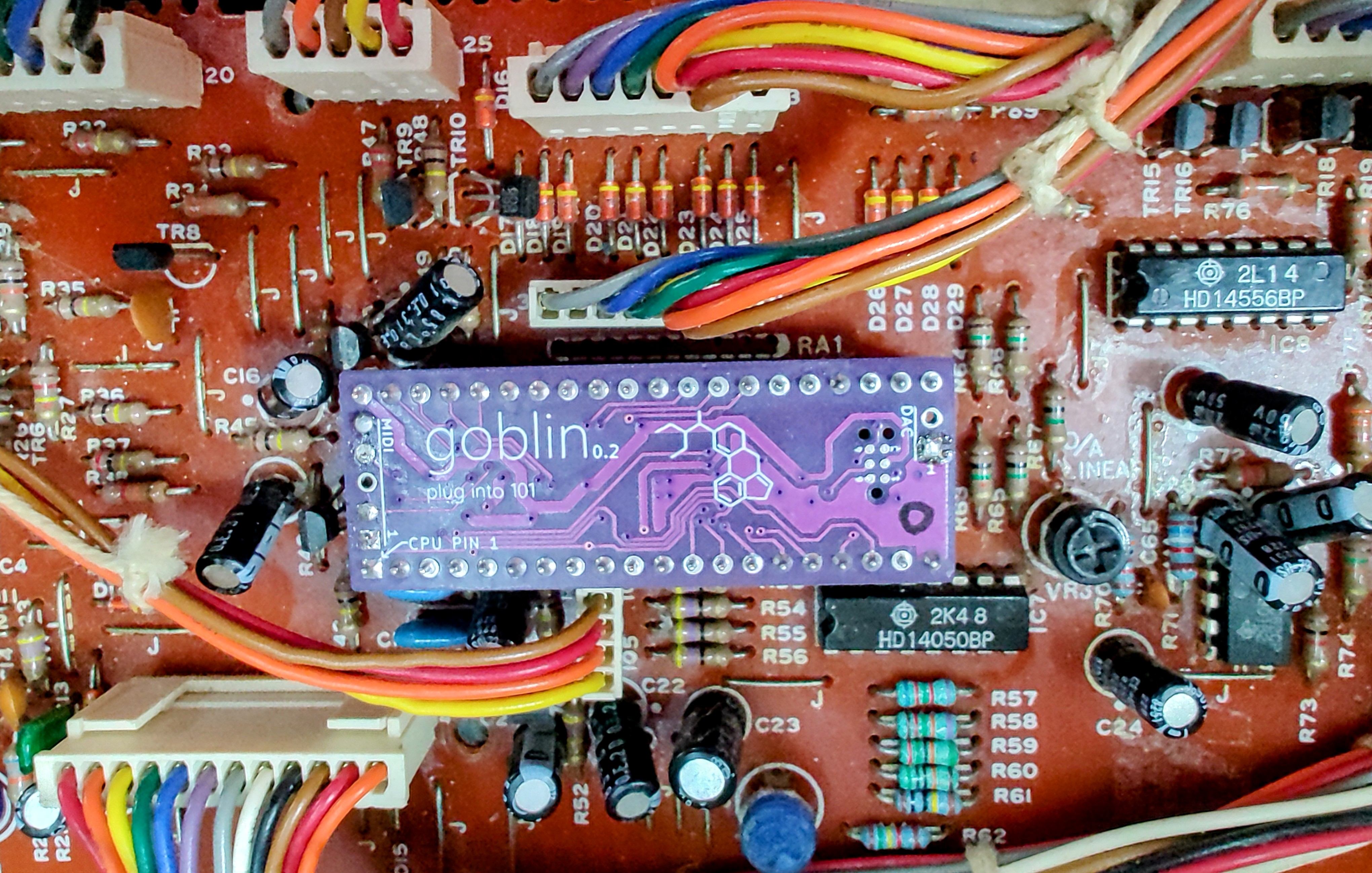
The Goblin should be seated in a suitable 40-pin IC socket in the orientation shown. If installing in an SH-101, this means desoldering the original CPU and installing a socket in its place.
There are no further modifications required. Components X1 and C19 on the SH-101 / RE-101 main board aren’t needed for the Goblin, so you don’t need to fit these if building the RE-101 (but are fine left in place if already present).
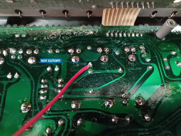
Wiring
Configuration
To enter configuration mode, hold KEY TRANSPOSE and U&D together. The respective LEDs for KEY TRANSPOSE and U&D flash together slowly. Whenever a configuration change is made using any of the steps shown below, the Goblin acknowledges the change by briefly flashing the KEY TRANSPOSE and U&D LEDs more rapidly. Press KEY TRANSPOSE to exit configuration mode.
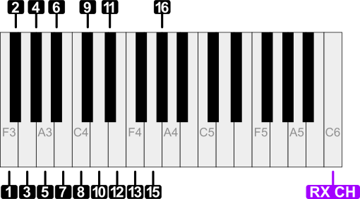
MIDI Receive Channel
When in Configuration Mode, hold down the key “RX CH” shown, and then while holding that key, simultaneously press the key corresponding with the desired MIDI receive channel.
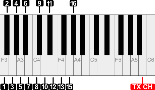
MIDI Transmit Channel
When in Configuration Mode, hold down the key “TX CH” shown, and then while holding that key, simultaneously press the key corresponding with the desired MIDI transmit channel.
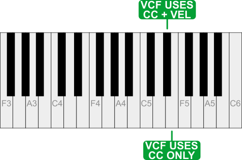
MIDI VCF control
There are two modes of VCF control via MIDI offered:
- Control of VCF using Continuous Controller (CC) #74
- Control of VCF using CC #74 in combination with note-on velocity
When in Configuration Mode, press the key corresponding with the desired mode.
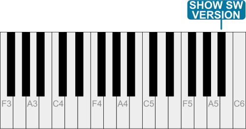
Display firmware version
Firmware Update
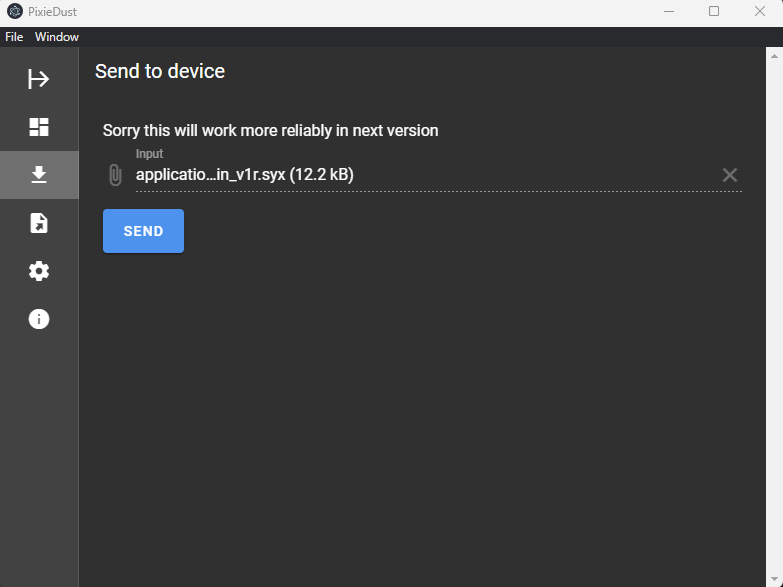
The firmware may be updated via MIDI using a Goblin firmware .syx file. A suitable tool to transfer the firmware file is PixieDust which may be obtained from https://github.com/sunflowr/pixiedust/releases.
Hold PLAY and HOLD together while turning on power. All LEDs above the buttons will flash continually. This indicates that the Goblin is ready to receive the firmware update.
In the PixieDust application ensure that the correct MIDI interface is selected in the Settings section. The default 250ms pause setting works fine with the Goblin. In the Send to device section, choose the .syx file and then hit SEND. The LEDs will start to illuminate sequentially in a ‘chase’ fashion while the firmware transfers. When finished, all LEDs will briefly flash rapidly to indicate success. If an error occurs, the LEDs flash at a slow rate.
Following successful firmware update, the Goblin switches to normal operation.